


 157 / 396

NON-FERROUS
PLASTICS/COMPOSITES
NON-FERROUS
PLASTICS/COMPOSITES
157
www.kyocera-sgstool.com
END MILLS
END MILLS
47
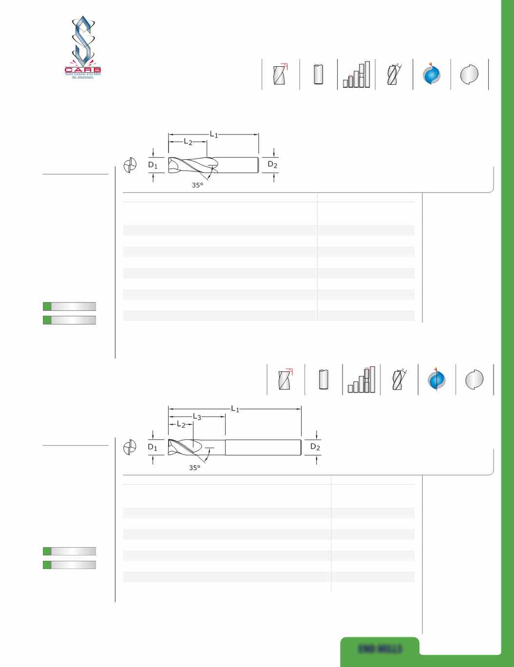
FRACTIONAL SERIES
inch
EDP NO.
CUTTING
DIAMETER
D
1
LENGTH
OF CUT
L
2
OVERALL
LENGTH
L
1
SHANK
DIAMETER
D
2
UNCOATED
Ti-NAMITE-B
(TiB
2
)
1/8
3/8
1-1/2
1/8
34620
34660
3/16
9/16
2
3/16
34621
34661
1/4
3/4
2-1/2
1/4
34622
34662
5/16
13/16
2-1/2
5/16
34623
34663
3/8
1
2-1/2
3/8
34624
34664
1/2
1-1/4
3-1/4
1/2
34625
34665
5/8
1-5/8
3-3/4
5/8
34626
34666
3/4
1-5/8
4
3/4
34627
34667
1
2
4-1/2
1
34628
34668
47L
FRACTIONAL SERIES
inch
EDP NO.
CUTTING
DIAMETER
D
1
LENGTH
OF CUT
L
2
OVERALL
LENGTH
L
1
SHANK
DIAMETER
D
2
REACH
L
3
UNCOATED
Ti-NAMITE-B
(TiB
2
)
1/4
3/8
4
1/4
2-1/8
34640
34678
3/8
1/2
4
3/8
2-1/8
34641
34679
1/2
5/8
6
1/2
2-1/8
34642
34680
1/2
5/8
6
1/2
3-3/8
34643
34681
5/8
3/4
6
5/8
2-3/8
34644
34682
5/8
3/4
6
5/8
3-3/8
34645
34683
3/4
1
6
3/4
2-1/2
34646
34684
3/4
1
6
3/4
3-3/8
34647
34685
FRACTIONAL
S-Carb
®
• Circular land reduces
edge aggressiveness
for varied speed and
feed rates
• 2 Flutes effectively
manage the large size
and volume of chips
produced during the
aggressive machining
process
• Excellent balance
at high speeds and
aggressive plunging
capability
• Recommended for
materials ≤ 150 Bhn
(≤ 7 HRc)
• Circular land reduces
edge aggressiveness
for varied speed and
feed rates
• 2 Flutes effectively
manage the large size
and volume of chips
produced during the
aggressive machining
process
• Excellent balance
at high speeds and
aggressive plunging
capability
• Necked design with
blended diameter
transitions provide
clearance to reach
• Recommended for
materials ≤ 150 Bhn
(≤ 7 HRc)
POS
2
POS
2
TOLERANCES
(inch)
1/8–3/16
DIAMETER
D
1
=
+0.0000/–0.00032
D
2
=
h
6
1/4–3/8
DIAMETER
D
1
=
+0.0000/–0.00035
D
2
=
h
6
1/2–5/8
DIAMETER
D
1
=
+0.0000/–0.00043
D
2
=
h
6
3/4–1
DIAMETER
D
1
=
+0.0000/–0.00051
D
2
=
h
6
TOLERANCES
(inch)
1/4–3/8
DIAMETER
D
1
=
+0.0000/–0.00035
D
2
=
h
6
1/2–5/8
DIAMETER
D
1
=
+0.0000/–0.00043
D
2
=
h
6
3/4–1
DIAMETER
D
1
=
+0.0000/–0.00051
D
2
=
h
6
®
For patent
information visit
www.ksptpatents.com
For patent
information visit
www.ksptpatents.com