


 158 / 396

NON-FERROUS
PLASTICS/COMPOSITES
NON-FERROUS
PLASTICS/COMPOSITES
158
www.kyocera-sgstool.com
END MILLS
END MILLS
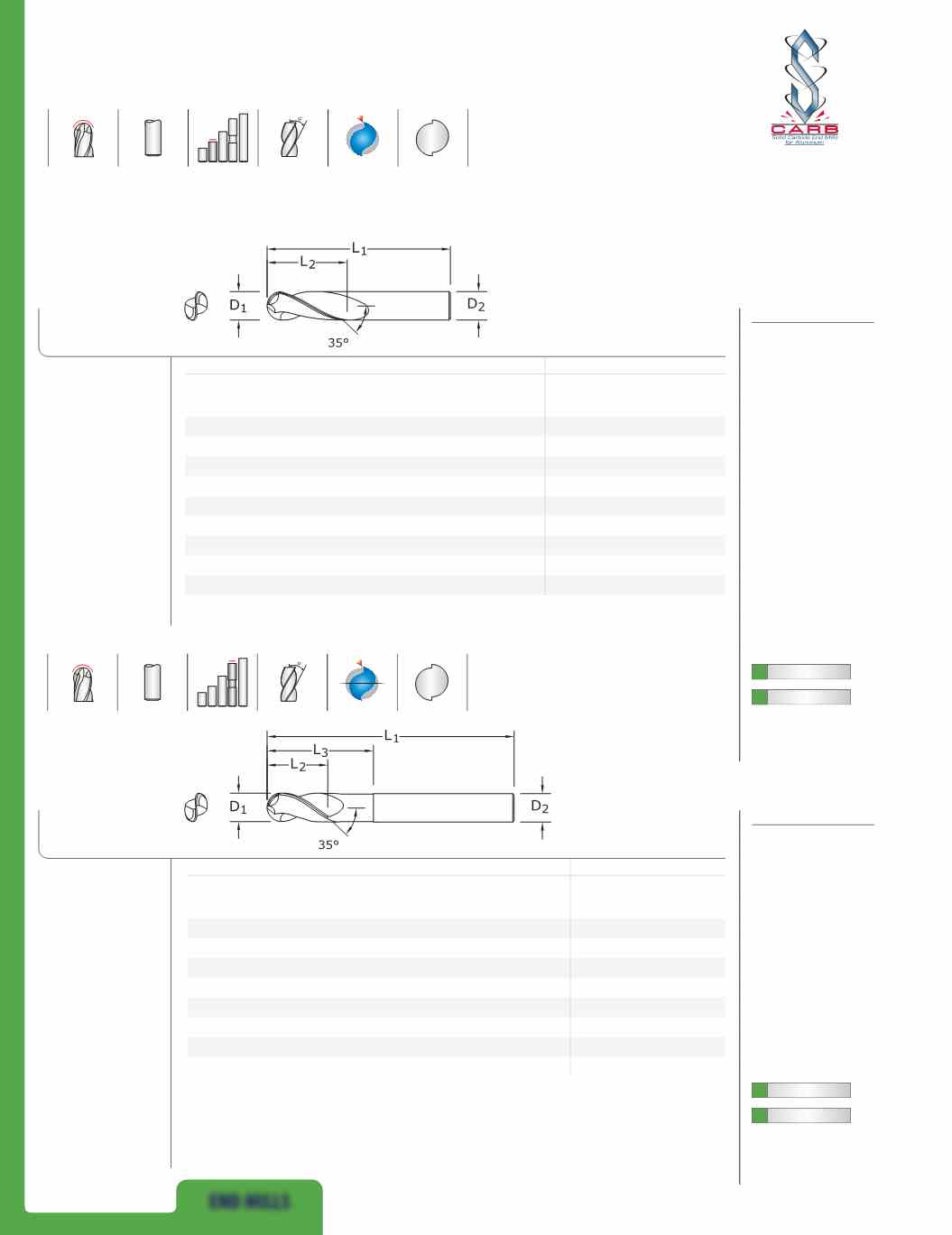
47B
FRACTIONAL SERIES
inch
EDP NO.
CUTTING
DIAMETER
D
1
LENGTH
OF CUT
L
2
OVERALL
LENGTH
L
1
SHANK
DIAMETER
D
2
UNCOATED
Ti-NAMITE-B
(TiB
2
)
1/8
3/8
1-1/2
1/8
34630
34669
3/16
9/16
2
3/16
34631
34670
1/4
3/4
2-1/2
1/4
34632
34671
5/16
13/16
2-1/2
5/16
34633
34672
3/8
1
2-1/2
3/8
34634
34673
1/2
1-1/4
3-1/4
1/2
34635
34674
5/8
1-5/8
3-3/4
5/8
34636
34675
3/4
1-5/8
4
3/4
34637
34676
1
2
4-1/2
1
34638
34677
47LB
FRACTIONAL SERIES
mm
EDP NO.
CUTTING
DIAMETER
D
1
LENGTH
OF CUT
L
2
OVERALL
LENGTH
L
1
SHANK
DIAMETER
D
2
REACH
L
3
UNCOATED
Ti-NAMITE-B
(TiB
2
)
1/4
3/8
4
1/4
2-1/8
34650
34686
3/8
1/2
4
3/8
2-1/8
34651
34687
1/2
5/8
6
1/2
2-1/8
34652
34688
1/2
5/8
6
1/2
3-3/8
34653
34689
5/8
3/4
6
5/8
2-3/8
34655
34691
5/8
3/4
6
5/8
3-3/8
34654
34690
3/4
1
6
3/4
2-1/2
34656
34693
3/4
1
6
3/4
3-3/8
34657
34692
FRACTIONAL
S-Carb
®
POS
2
POS
2
®
• Circular land reduces
edge aggressiveness for
varied speed and feed
rates
• 2 Flutes effectively
manage the large size
and volume of chips
produced during the
aggressive machining
process
• Excellent balance at high
speeds and aggressive
plunging capability
• Ball nose design ideal for
finishing operations in
complex workpieces
• Recommended for
materials ≤ 150 Bhn
(≤ 7 HRc)
• Circular land reduces
edge aggressiveness for
varied speed and feed
rates
• 2 Flutes effectively
manage the large size
and volume of chips
produced during the
aggressive machining
process
• Excellent balance at high
speeds and aggressive
plunging capability
• Necked design with
blended diameter
transitions provide
clearance to reach
• Ball nose design ideal for
finishing operations in
complex workpieces
• Recommended for
materials ≤ 150 Bhn
(≤ 7 HRc)
TOLERANCES
(inch)
1/8–3/16
DIAMETER
D
1
=
+0.0000/–0.00032
D
2
=
h
6
BALL RADIUS
+.0005/–.0005
1/4–3/8
DIAMETER
D
1
=
+0.0000/–0.00035
D
2
=
h
6
BALL RADIUS
+.0005/–.0005
1/2–5/8
DIAMETER
D
1
=
+0.0000/–0.00043
D
2
=
h
6
BALL RADIUS
+.0005/–.0005
3/4–1
DIAMETER
D
1
=
+0.0000/–0.00051
D
2
=
h
6
BALL RADIUS
+.0005/–.0005
TOLERANCES
(inch)
1/4–3/8
DIAMETER
D
1
=
+0.0000/–0.00035
D
2
=
h
6
BALL RADIUS
+.0005/–.0005
1/2–5/8
DIAMETER
D
1
=
+0.0000/–0.00043
D
2
=
h
6
BALL RADIUS
+.0005/–.0005
3/4–1
DIAMETER
D
1
=
+0.0000/–0.00051
D
2
=
h
6
BALL RADIUS
+.0005/–.0005
For patent
information visit
www.ksptpatents.com
For patent
information visit
www.ksptpatents.com